DC Circuits
Homework Solutions Questions 2, 4, 5, 6, 8, 9, 28
Problems 1, 2, 14, 15, 19, 20, 28, 41, 42, 45, 50
Q2 Under what condition does the potential difference across the terminals of a battery equal its emf? Can the terminal voltage ever exceed the emf?
When there is no load, the terminal voltage is the same as the emf. The terminal voltage can never exceed the emf.Q4 Two sets of Christmas-tree lights are available. For set A, when one bulb is removed (or burns out), the remaining bulbs remain illuminated. For set B, when one bulb is removed, the remaining bulbs do not operate. Explain the differnce in wiring of the two sets.
Set A is connected in parallel.
Set B is connected in series.
Q5 How would you connect resistors so that the equivalent resistance is larger than the individual resistance?
Resistors in series will provide an equivalent resistance that is larger than the largest individual resistance.Q6 How would you connect resistors so that the equivalent resistance is smaller than the individual resistance?
Resistors in paralled will provide an equivalent resistance that is smaller than the smallest individual resistance.Q8 When resistors are connected in series, which of the following would be the same for each resistor: potential difference, current, power?
Resistors in series share a common current.Q9 When resistors are connected in parallel, which of the following would be the same for each resistor: potential difference, current, power?
Resistors in parallel share a common voltage or potential difference.Q28 A series circuit consists of three identical lamps connected to a battery as in Figure 28.29. When the switch S is closed, what happens
(a) to the intensities of lamps A and B;
(b) to the intensity of lamp C;
(c) to the current in the circuit; and
(d) to the voltage drop across the three lamps?
(e) Does the power dissipated in the circuit increase, decrease or remain the same?
(a) Lamps A and B (the two on the left) experience the full voltage instead of 2/3 of it so their intensities INCREASE.
(b) The intensity of lamp C becomes ZERO.
(c) The current INCREASES since the equivalent resistance of the circuit is now only 2/3 what it was before the switch was closed.
(d) The voltage drop across each of the lamps initially was [(1/3) E] . After the switch is closed, the voltage drop across each of the first two lamps is [(1/20) E] while the voltage across the third lamp is zero.
(e) The current increases so the power, too, INCREASES.
28.1 A battery with an emf of 12 V and an internal resistance of 0.90 ohms is connected across a load resistor R.
(a) If the current in the circuit is 1.4 A, what is the value of R?
(b) What power is dissipated in the internal resistance of the battery?

I = 1.4 A = 12 V / [R + 0.90
]
[R + 0.90
R + 0.90
R = (8.57 - 0.90)
R = 7.67
28.2 A 9.00-V battery deliver 117 mA when connected to a 72.0-ohm laod. Determine the internal resistance of the battery.
0.117 A = 9.0 V / [72.0
[72.0
72.0
Rint = (76.9 - 72.0)
Rint = 4.9
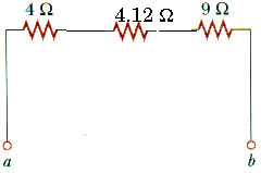
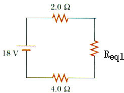
28.14 (a) Find the equivalent resistance between points a and b in Figure P28.14
(b) If a potential difference of 34 V is applied between points a and b, calculate the current in each resistor.
First, replace the 7-
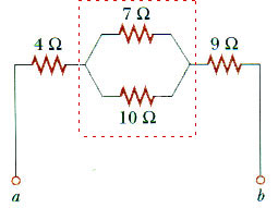
1/Req1 = 1/7
1/Req1 = (0.143 + 0.100)(1/
1/Req1 = 0.243 (1/
Req1 = (1/0.243
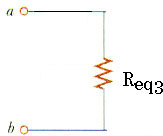
Now these three resistors are in series so we can replace them with a single equivalent resistor Req2;
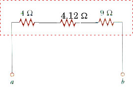
Req2 = 4
Req2 = 17.12
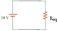
Now we know the equivalent resistance. If a voltage difference of 34 V is placed across terminals a and b, current of
I = V/ R I = 34 V / 17.12
I = 1.986 A
will flow out of the battery. This same current flows through the 4-
V = I Req2 V = (1.986 A)(4.12
V = 8.18 V
That voltage is also the common voltage across the ends of the7-
I = V / R I(7
I(10
Notice that the sum of these two voltages, Isum = 1.17 A + 0.82 A = 1.99 A is (essentially) the same as the current through the 4-
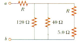
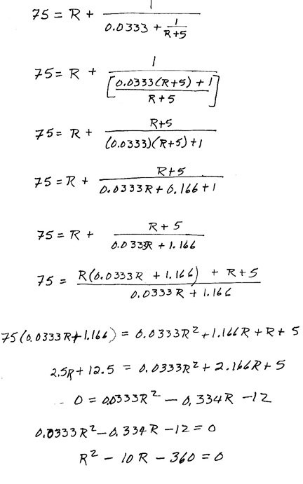
28.15 The resistance between terminals a and b inFigure P28.15 is 75-ohms. If the resistors labeled R have the same value, determine R.
First, replace the R and the 5.0
Since those are in series, this equivalent resistor has a value of
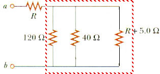
Req1 = R + 5.0 Now we have three resistors in parallel.
Those resistors are the 120-
1/Req2 = [1/120 + 1/40 + 1/(R + 5)][1/ 1/Req2 = [0.00833 + 0.025 + 1/(R + 5)][1/
1/Req2 = [0.0333 + 1/(R + 5)][1/
Req2 = (1/[0.0333 + 1/(R + 5)])
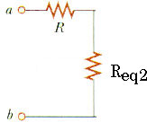
Now we have R and Req2 in series so it is very easy to calculate this final equivalent resistor, Req3;
Req3 = R + Req2
This resistance is 75
Req3 = R + Req2 Req2 = (1/[0.0333 + 1/(R + 5)])
75
28.19 Calculate the power dissipated in each resistor in the circuit of Figure P28.19.
To find the power we first need to find the current through each resistor and the voltage across each resistor. This means finding the equivalent resistor and then working our way back.
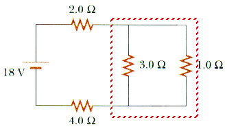
1/Req1 = 1/3
1/Req1 = 4/3
Req1 = (3/4)
Req1 = 0.75
Now these are in series so we can replace them with the final equivalent resistor Req by
Req = 2 Req = 6.75
The current that comes from the battery is
I = V/Req I = 18 V / 6.75
I = 2.67 A
That is also the current through the 2-
P = I V = I2 R P2 = I22 R2
P2 = (2.67 A)2 (2
P4 = I42 R
P4 = (2.67 A)2 (4
We can easily find the voltage across Req1 which is also the voltage across the 1-
V = I Req1 V = (2.67 A) (0.75
P = I V = (V/R) V = V2/R
P1 = (2 V)2/1
P3 = (2 V)2/3
We're done now. But it's still "nice" to check our answers or to check the Physics of the power produced by the battery and the total power dissipated by all the resistors.
Pbat = I V = (2.67 A)(18 V) = 48.06 W Ptot = P1 + P2 + P3 + P4
Ptot = 4 W + 14.26 W + 1.25 W + 28.52 W
Ptot = 48.03 W
And, those are the same (to within "round-off error") as the must be.
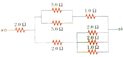
28.20 Determine the equivalent resistance between the terminals a and b for the network illustrated inFigure P28.20.
The three resistors in the lower right corner are in parallel. Sometimes it helps to simply re-draw a circuit.
Re-drawn like this, it should be clear that the three resistors in the lower right corner are in parallel. Let's begin by replacing them with an equivalent resistor Req1.
1/Req1 = 1/2
1/Req1 = (0.5 + 0.5 + 1.0)(1/
1/Req1 = 2.0 (1/
Req1 = 0.5
Req2 = 2.0
Req2 = 2.5
Now we move our attention to the 3.0-
1/Req3 = 1/3
1/Req3 = (0.33 + 0.20)(1/
1/Req3 = 0.53 (1/
Req3 = (1/0.53)
Req3 = 1.89
Req4 = Req3 + 1
Req4 = 1.89
Req4 = 2.89
1/Req5 = 1/Req4 + 1/Req2
1/Req5 = 1/2.89
1/Req5 = (0.346 + 0.4)(1/
1/Req5 = 0.746 (1/
Req5 = (1/0.746)
Req5 = 1.34
Req = 2.0
Req = 2.0
Req = 3.34
Req = 3.34
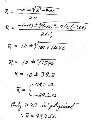
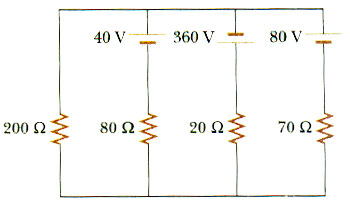
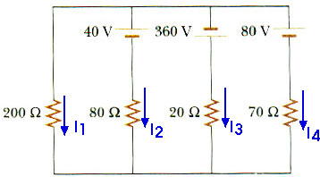
28.28 In the circuit of Figure P28.28, determine the current in each resistor and the voltage across the 200-ohm resistor.
Okay, here it is! This requires the application of Kirchoff's Rules. Begin by assigning a current through each of the resistors.
Apply Kirchoff's Junction Rule at the two junctions.
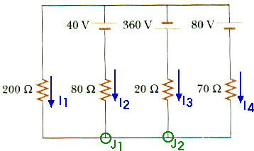
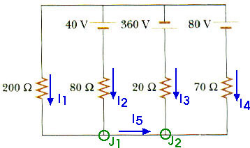
J1: I1 + I2 = I5
J2: I5 + I3 + I4 = 0
I1 + I2 + I3 + I4 = 0
Certainly one or more of our currents will turn out to be negative. (That's okay!) We have four unknowns and only one equation. We will have to get three more equations from Kirchoff's Loop Rule.
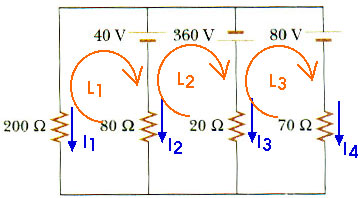
L1: - 40 V = I2 (80
L2: 40 V - 360 V = I3 (20
L3: - 360 V - 80 V = I4 (70
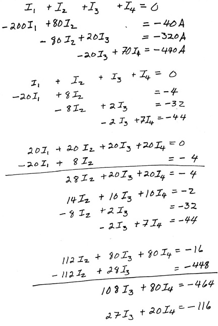
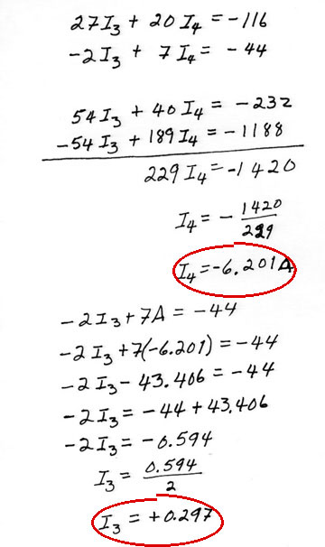
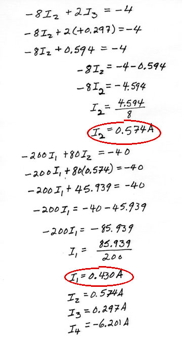
We are finished with the "Physics" of this problem. It's "just" math from here on. We have four unknowns so now we need only four equations,
I1 + I2 + I3 + I4 = 0 - 40 V = I2 (80
40 V - 360 V = I3 (20
- 360 V - 80 V = I4 (70
80 V = I4 (70
Deciding how to choose a "loop" sometimes seems difficult. Any continuous loop is a candidate. We might have used a loop around the outside of the entire circuit diagram.

L4: 80 V = I4 (70
28.41 A fully charged capacitor stores 12 J of energy. How much energy remains when its charge has decreased to half its original value?
E = (1/2) Q2 / C When the carge decreases to one-half, the energy has decreased to one-fourth.
28.42 Consider a series RC circuit (Figure 28.15) for which R = 1.0 megaohms, C = 5.00 microfarads, and E = 30.0 V. Find
(a) the time constant of the circuit and
(b) the maximum charge on the capacitor after the switch is closed.
(c) If the switch is closed at time t = 0, find the current in the resistor 10.0 s later.
(a) the time constant of the circuit
= R C
(b) the maximum charge on the capacitor after the switch is closed.
C = Q/V Qf = C V
Qf = (5 x 10 - 6 f)(30 V) [(V/C)/f]Qf = 0.00015 C
Qf = 1.5 x 10 - 4 C
(c) If the switch is closed at time t = 0, find the current in the resistor 10.0 s later.
Io = V/R = 30 V/1 x 106 Io = 3 x 10 - 5 A

I(5s) = (3 x 10 - 5 A) EXP[ - (5s/10s)]
I(5s) = (3 x 10 - 5 A) EXP[ - 2]
I(5s) = (3 x 10 - 5 A) (0.135)
I(5s) = 4.05 x 10 - 6 A
I(5s) = 4.05
A
28.45 A 4.00 megaohm resistor and a 3.00 microfarad capacitor are connected in series with a 12.0 V power supply.
(a) What is the time constant for the circuit?
(b) Express the current in the circuit and the charge on the capacitor as functions of time.
Io = V/R = 12 V/4 x 106
Io = 3 x 10 - 6 A
Io = 3
i(t) = (3
C = Q/V
Qf = C V
Qf = (3 x 10 - 6 f)(12 V) [(C/V)/f]
Qf = 36 x 10 - 6 C
Qf = 36
q(t) = (36
28.50 A capacitor in an RC circuit is charged to 60% of its maximum value in 0.90 s. What is the time constant of the circuit?
0.6 Qf = Qf [ 1 - EXP( - 0.9 s/
0.6 = 1 - EXP( - 0.9 s/
EXP( - 0.9 s/
EXP( - 0.9 s/
ln[EXP( - 0.9 s/
ln[EXP( - 0.9 s/
- 0.9 s/
0.9 s/
0.9 s/0.916 =


Ch29, ToC
Return to ToC (c) Doug Davis, 2002; all rights reserved